Copyright © 2025 Chuangming Coupling (Jiangsu) Co.,Ltd.
The coupling device alters the rotational inertia to avoid resonance.
2026-07-03
During operation, the periodic load of the coupling is a typical load form in mechanical transmission. The variation frequency of the periodic load of the coupling should be offset from the natural frequency of the transmission shaft system. Generally, this is achieved by changing the natural frequency of the shaft system to avoid resonance. Changing the natural frequency of the shaft system usually involves altering the rotational inertia or stiffness of the shaft system. Rotational inertia is related to the mechanical structure, and any change in torque can produce a damping effect. It is difficult to achieve this by changing the rotational inertia, while the stiffness of the shaft system can be easily changed. The purpose of the coupling is to change the stiffness of the shaft system to avoid resonance.
The bearing seat undergoes long-term vibration and shifts position. Since vibration generated by large fans is inevitable, this can easily cause slight loosening of the fastening bolts of the base, resulting in slight misalignment and vibration. After the bearing seat and the base are bolted together, they should be closely adhered, and a 0.05mm feeler gauge should not be able to be inserted. The main motor itself causes this. Large motors have relatively good requirements for dynamic balance. Due to various reasons during long-term operation, the dynamic balance of the motor is disrupted and misalignment is required. Improper operation during start-stop or speed-up/down speed processes, uneven thermal expansion, or staying in the critical zone for too long.
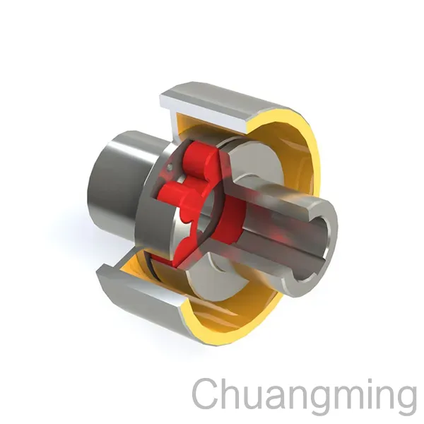
There is also obvious vibration on the output side of the motor. By disengaging the coupling between the induced draft fan and the motor, the motor runs alone, and the vibration disappears. The coupling center should be re-aligned and adjusted, and the eccentricity between the shafts of the induced draft fan and the motor should be reduced. Reasonable gaps should be reserved between the induced draft fan and the motor coupling. With changes in load, the amplitude is smaller during idle operation and larger during full load. The greater the radial displacement of the two shaft centers, the greater the vibration. The radial displacement of the two shaft centers should not exceed 0.03mm, and the contact between the two half couplings should be tight. The coupling is fixed by the key slot type, suitable for high-torque transmission. To prevent axial sliding, it is usually fixed together with positioning screws and locking screws.
During operation, the periodic load of the coupling is a typical load form in mechanical transmission. The variation frequency of the periodic load of the coupling should be offset from the natural frequency of the transmission shaft system. Generally, this is achieved by changing the natural frequency of the shaft system to avoid resonance. Changing the natural frequency of the shaft system usually involves altering the rotational inertia or stiffness of the shaft system. Rotational inertia is related to the mechanical structure, and any change in torque can produce a damping effect. It is difficult to achieve this by changing the rotational inertia, while the stiffness of the shaft system can be easily changed. The purpose of the coupling is to change the stiffness of the shaft system to avoid resonance.
The bearing seat undergoes long-term vibration and shifts position. Since vibration generated by large fans is inevitable, this can easily cause slight loosening of the fastening bolts of the base, resulting in slight misalignment and vibration. After the bearing seat and the base are bolted together, they should be closely adhered, and a 0.05mm feeler gauge should not be able to be inserted. The main motor itself causes this. Large motors have relatively good requirements for dynamic balance. Due to various reasons during long-term operation, the dynamic balance of the motor is disrupted and misalignment is required. Improper operation during start-stop or speed-up/down speed processes, uneven thermal expansion, or staying in the critical zone for too long.
There is also obvious vibration on the output side of the motor. By disengaging the coupling between the induced draft fan and the motor, the motor runs alone, and the vibration disappears. The coupling center should be re-aligned and adjusted, and the eccentricity between the shafts of the induced draft fan and the motor should be reduced. Reasonable gaps should be reserved between the induced draft fan and the motor coupling. With changes in load, the amplitude is smaller during idle operation and larger during full load. The greater the radial displacement of the two shaft centers, the greater the vibration. The radial displacement of the two shaft centers should not exceed 0.03mm, and the contact between the two half couplings should be tight. The coupling is fixed by the key slot type, suitable for high-torque transmission. To prevent axial sliding, it is usually fixed together with positioning screws and locking screws.